
VLANs? That doesn’t sound like a Web Design or Development theme!” And you’re right! From now on, I’m adding Networking to the Blog categories, and VLANs are going to be my first post.
Virtual? LAN?
Of course, we all know what a LAN is. It is a network which connects computers and other devices and is typically located in our home or office building. LAN enables our devices to share data with each other and access each other’s resources.
So, LANs are cool, but as always, there’s room for some improvement. Imagine your company has marketing, production and management departments. In a traditional LAN-Sense, you would have to either:
1. Put them all on the same LAN
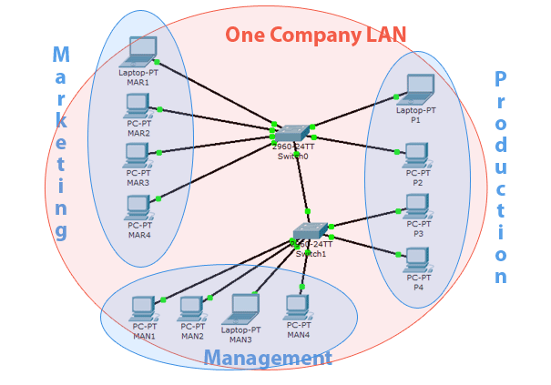
Of course, you already know what this does. It reduces network security, as the production department now has access to management resources. It also decreases available bandwidth for each department.
2. Physically separate their LANs
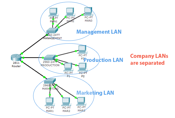
At first, you might think that the second design is very good, but there are disadvantages. One huge disadvantage is poor flexibility. What happens if the place runs out on the production switch for example? What if the people who work in the departments are spread across two floors or buildings? What if the new marketing employee comes to the part of the building that doesn’t have any marketing network infrastructure?
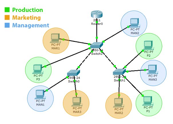
That’s where the VLAN comes in! VLAN enables the hosts to communicate with each other without being connected to the same network switch. You can change hosts’ LAN membership through software instead of physically relocating them. So, you can for example have 3 ‘marketing’ hosts on the first of your building, another five on the second floor, and so on:
The advantages are pretty clear:
- Scalability – Out of space for that new ‘production’ employee on the first floor? Just put him on a different floor and assign him to the production VLAN
- Security – Users cannot access hosts in other VLANs by default even if they’re connected to the same switch.
- Cost – We don’t need frequent upgrades to the network infrastructure. Also, existing bandwidth is used more efficiently.
Now that we know VLANs are cool and that you should be using them, let’s take a quick overview of basic VLAN terms, what they mean and of course, how to configure VLANs on Cisco switches.
Basic VLAN terms
- Access port – this is the switch port that „belongs” to a certain VLAN. Devices that connect to this port will be a part of the VLAN specified by the port configuration.
- Trunk – a trunk link is a link which carries more than one VLAN. A trunk link is established between two network devices and enables us to extend the VLAN across our entire network. A trunk port is a port that has been configured with trunking mode and is connected to another trunk port via the trunk link.
- Tagged frames – when the switch receives a frame that is destined for a trunk link it adds the information about which VLAN the frame belongs to (tags the frame).
- Inter-VLAN routing – every VLAN is a separate network, just like they were physically separated. So if we want the traffic to be able to get from one VLAN to the other we must use routing.
Let us now try and configure a simple network with VLANs in Packet Tracer.
I use Cisco Packet Tracer simply because I think most readers have it and are familiar with it and it’s simple to use. If you don’t have Packet Tracer, I might suggest getting the GNS3, however, setting it up and using it will be up to you as we do not have time to get into it right now.
VLAN Configuration
This is the topology we will be creating:
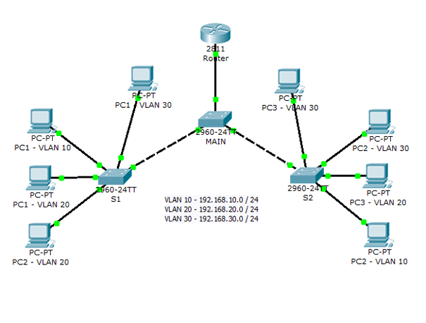
And this is the network addressing scheme:
- VLAN for Management department: 192.168.10.0 / 24
- Marketing department VLAN: 192.168.20.0 / 24
- Production department VLAN: 192.168.30.0 / 24
We will use the Router on a Stick method for Inter-VLAN routing and will use the first address in each network for router subinterface addresses. Confused? Don’t worry, we’ll get to that in a moment. For now, all you need to know is that you must assign each PC default gateway and we’ll use the first address in the network for that.
You can go about creating the topology in a number of ways. My first step was to determine which switch ports will be used for which VLANs. We have 24 fast ethernet switch ports, and 3 VLANs, so I decided to use 8 ports for each VLAN. VLAN 10 will use ports 1-8, VLAN 20 ports 9-16 and VLAN 30 ports 17-24. For Trunk links, we will use 2-gigabit ethernet ports the switch Cisco Catalyst 2960 provides.
So the first step is to connect the hosts to the switches on the ports we agreed. Hosts for VLAN 10 (for the Management department) should connect to ports 1-8, VLAN 20 to ports 9 to 16, and VLAN 30 hosts should connect to ports 17-24. As we already know, we must use straight-through cables for connecting hosts to switches. We also use a straight-through cable for connecting the router to the switch.
To connect the switches we use a crossover cable and Gigabit Ethernet ports.
After that let’s configure the hosts because that is the easiest part. Click on the host icon in Packet tracer to open host properties. Switch to the „Desktop” module, and click IP configuration.
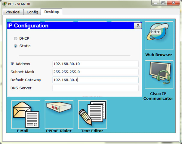
Host for VLAN 30. For the first host, IP Address is 10 in the last octet, for the second host 11, etc. The default gateway address is as we said, the first address in the network.
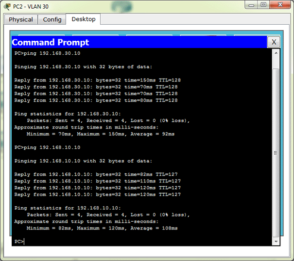
After we configure the hosts we can check for their connectivity by pinging from the Desktop > Command Prompt:
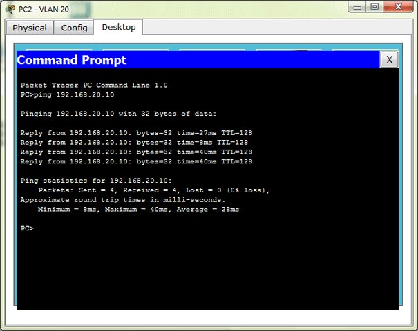
Remember, for now, you can only ping the hosts that are in the same VLAN and on the same switch.
After we configure all the hosts now the fun part starts: Switch configuration.
It’s easier to first configure the S1 and S2. Their configuration is almost the same so, I will show here only the S1 configuration. First, we configure Access ports for VLANs 10, 20, 30:
Switch>enable
Switch#conf t
Enter configuration commands, one per line.  End with CNTL/Z.
Switch(config)#int range fa0/1-8
Switch(config-if-range)#sw
Switch(config-if-range)#switchport mode
Switch(config-if-range)#switchport mode acc
Switch(config-if-range)#switchport mode access
Switch(config-if-range)#switchport access ?
vlan  Set VLAN when interface is in access mode
<1-1005>  VLAN ID of the VLAN when this port is in access mode
Switch(config-if-range)#switchport access vlan 10
% Access VLAN does not exist. Creating vlan 10

Switch(config-if-range)#int range fa0/9-16
Switch(config-if-range)#switchport mode access
Switch(config-if-range)#switchport access vlan 20
% Access VLAN does not exist. Creating vlan 20
Switch(config-if-range)#int range fa0/17-24
Switch(config-if-range)#switchport mode access
Switch(config-if-range)#switchport access vlan 30
% Access VLAN does not exist. Creating vlan 30
Now, that was simple, wasn’t it? Using the Interface range command we can configure a bunch of ports at once. When we assign the VLAN to a port if it doesn’t exist switch creates it for us. Of course, we can also create VLAN ourselves, like so:
Switch#conf t
Enter configuration commands, one per line. End with CNTL/Z.
Switch(config)#vlan 40
Switch(config-vlan)#?
VLAN configuration commands:
exit Apply changes, bump revision number, and exit mode
name Ascii name of the VLAN
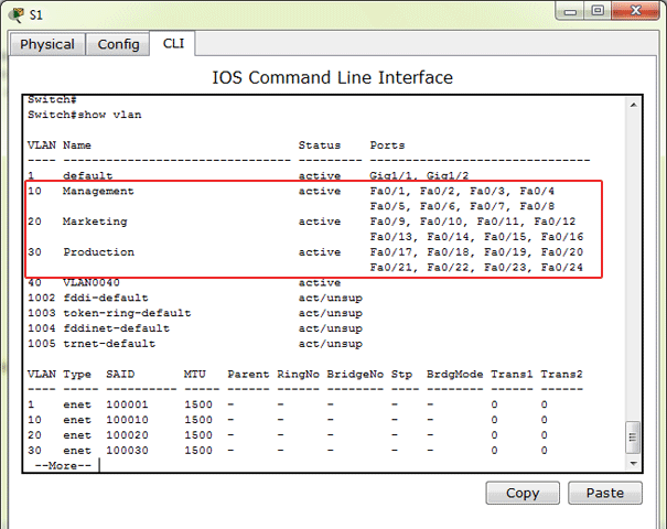
no Negate a command or set its defaultsSee? When we create the VLAN we can also assign it a name. So, let’s assign a name to the VLANs the IOS automatically created for us.
Switch(config-vlan)#vlan 10
Switch(config-vlan)#name Management
Switch(config-vlan)#vlan 20
Switch(config-vlan)#name Marketing
Switch(config-vlan)#vlan 30
Switch(config-vlan)#name Production
Now when we use the show vlan command we see the VLANs we created, their respective names, and the ports:
Because we have the hosts for each VLAN on another switch, we must create the Trunk link to the other switch. Remember, we connected the switches on the gigabit ports with a crossover cable, so let’s configure those ports. On S1 we only have 1 Gigabit ethernet port to configure:
Switch#conf t
Enter configuration commands, one per line.  End with CNTL/Z.
Switch(config)#interface gigabitEthernet 1/1
Switch(config-if)#switchport mode trunk

%LINEPROTO-5-UPDOWN: Line protocol on Interface GigabitEthernet1/1, changed state to down

%LINEPROTO-5-UPDOWN: Line protocol on Interface GigabitEthernet1/1, changed state to up

Switch(config-if)#switchport trunk allowed vlan 10,20,30
Switch(config-if)#
Ok, now the switch is able to carry VLAN traffic for VLANs 10, 20 and 30 over the trunk link to the other switches on the network. We also use the allowed VLAN command to limit the trunking to VLANs 10, 20 and 30.
We configure the S2 switch the same way:
S2>enable
S2#conf
S2#configure t
Enter configuration commands, one per line.  End with CNTL/Z.
S2(config)#int range fastEthernet 0/1-8
S2(config-if-range)#switchport mode access
S2(config-if-range)#switchport access vlan 10
% Access VLAN does not exist. Creating vlan 10
S2(config-if-range)#int range fastEthernet 0/9-16
S2(config-if-range)#switchport mode access
S2(config-if-range)#switchport access vlan 20
% Access VLAN does not exist. Creating vlan 20
S2(config-if-range)#int range fastEthernet 0/17-24
S2(config-if-range)#switchport mode access
S2(config-if-range)#switchport access vlan 30
% Access VLAN does not exist. Creating vlan 30
And the trunk:
S2(config)#interface gigabitEthernet 1/2
S2(config-if)#switchport mode trunk

%LINEPROTO-5-UPDOWN: Line protocol on Interface GigabitEthernet1/2, changed state to down

%LINEPROTO-5-UPDOWN: Line protocol on Interface GigabitEthernet1/2, changed state to up

S2(config-if)#sw tru all vlan 10,20,30
Now the switch I named „Main”. As you can see on the topology, Main doesn’t have any VLANs, but it’s Gigabit and Fast Ethernet 0/24 ports must be in the trunking mode to enable the tagged (VLAN) traffic to get from S1 to S2, and also for Inter-VLAN routing.
Main>en
Main#conf t
Main(config)#int rang
Main(config)#int range gi1/1-2
Main(config-if-range)#sw mo tru
Main(config-if-range)#sw tru all vlan 10,20,30
Main(config-if-range)#int fa0/24
Main(config-if)#sw mo tru
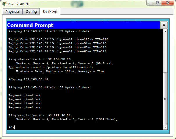
Main(config-if)#sw tru all vlan 10,20,30If you now try to ping other hosts in the same VLAN, you should be able to do it, no matter to which switch they are connected. But, still, you cannot access the hosts in different VLAN. That’s where the router comes in.
Now let’s configure the router. We must create subinterfaces on the router for each VLAN we want to route. So, we must create 3 subinterfaces and assign them IP addresses from the appropriate VLAN. Remember, the host’s default gateway address is the address of the appropriate router subinterface. This type of Inter-VLAN routing is called Router on a Stick.
Router subinterfaces recap:
- Fast Ethernet 0/0.10 – 192.168.10.1
- Fast Ethernet 0/0.20 – 192.168.20.1
- Fast Ethernet 0/0.30 – 192.168.30.1
Note the dot separating the name. It only has local significance, we can use any number. But it is wise to use the same number as VLAN, so we don’t get lost later. So, let’s do it:
Router#conf t
Enter configuration commands, one per line.  End with CNTL/Z.
Router(config)#int fa0/0.10

%LINK-5-CHANGED: Interface FastEthernet0/0.10, changed state to up
%LINEPROTO-5-UPDOWN: Line protocol on Interface FastEthernet0/0.10, changed state to up
Note: before we try to add an IP address we must define what encapsulation (standard for frame tagging) the router will use on a said subinterface. As you can see we only have dot1Q available, so we configure that and specify the VLAN ID for the subinterface:
Router(config-subif)#encapsulation ?
dot1Q  IEEE 802.1Q Virtual LAN
Router(config-subif)#encapsulation dot1Q ?
<1-1005>  IEEE 802.1Q VLAN ID
Router(config-subif)#encapsulation dot1Q 10
Router(config-subif)#ip address 192.168.10.1 255.255.255.0
We configure other subinterfaces on the same principle:
Router(config-subif)#int fa0/0.20

%LINK-5-CHANGED: Interface FastEthernet0/0.20, changed state to up

%LINEPROTO-5-UPDOWN: Line protocol on Interface FastEthernet0/0.20, changed state to up
Router(config-subif)#encapsulation dot1Q 20
Router(config-subif)#ip address 192.168.20.1 255.255.255.0
Router(config-subif)#int fa0/0.30

%LINK-5-CHANGED: Interface FastEthernet0/0.30, changed state to up

%LINEPROTO-5-UPDOWN: Line protocol on Interface FastEthernet0/0.30, changed state to up
Router(config-subif)#encapsulation dot1Q 30
Router(config-subif)#ip address 192.168.30.1 255.255.255.0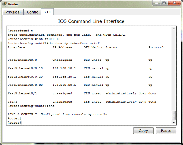
You may or may not believe it, but that’s it. If we now try to ping the host from a different VLAN you will see that it works.
So, in conclusion: VLANs are great, they are not so hard to configure and you should be using them.
Thank you, have fun when studying for certification and until next time!