
As you may or may not know, communication on the Internet uses packets for transmitting data. So, every time your computer communicates with a computer on the Internet, IP packets are used to transmit and receive data.
Your computer by itself can’t deliver the packets all the way to the destination, so it relies on other networking hardware on the way over to do its part. We could say that Routing is a process of selecting the best paths through the network for forwarding packets from the source to their destination.
I have to communicate with another computer! But he’s not in the same network as me! What do I do? Send the packets to the my default gateway! He IS in my network and hopefully, he WILL know what to do! 🙂
The FUN side of the story
So what does Router do? Simply put, Router forwards packets across different networks.
How come router can do that? Router receives our packet on one of it’s interfaces and examines it. Once the router has examined the packet, it knows the packet’s destination. Using the information in it’s Routing table router can then forward the packet either to the destination or to the next router on the packet’s journey.
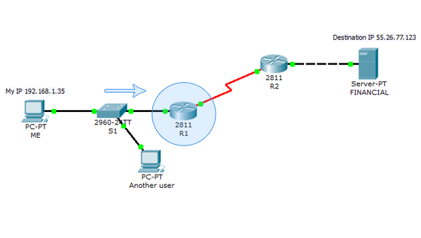
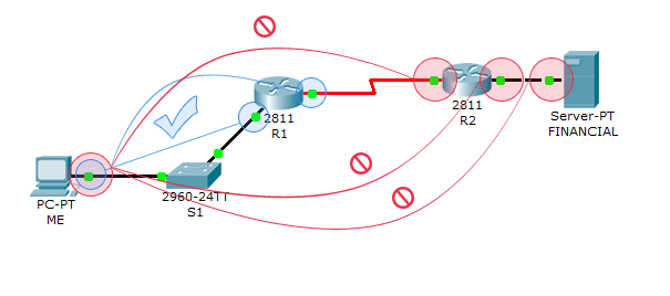
An example can work wonders. Let’s create a small network using the Cisco Packet tracer (of course, if you want you can use the GNS3):
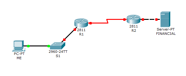
Just to show what Routers do, let’s create a simple network, just like the picture above. Let’s just say PC wants to verify that the server is online by using ping command. So, user from the PC must be able to send the packets to the server, and the server must be able to reply to those packets.
The addressing plan is:
- PC’s network that connects to R1 -> 192.168.1.0/24
- Network for link between routers -> 172.16.0.0/30
- Financial server’s network that connects to R2 -> 55.26.77.0/24
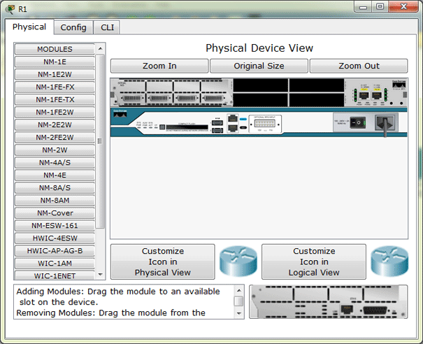
Remember, to use serial cable, we must first add the appropriate module to the router. How? Simply double-click the router, on the “Physical” card, turn it off by clicking the power switch, drag the appropriate card into an empty slot (for example NM-4A/S) and turn the router back on. 🙂
First, for illustrative purposes let’s configure the server with an IP address 55.26.77.123, and subnet mask 255.255.255.0
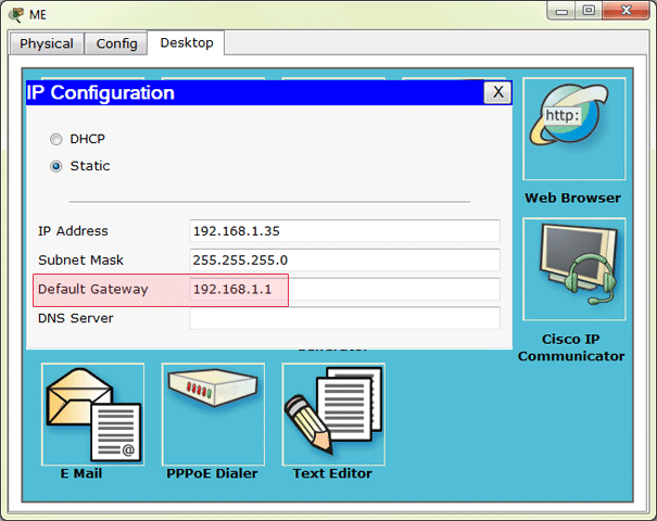
IP address of the host is 192.168.1.35, with subnet mask: 255.255.255.0. That’s easy to configure, no need to get into the details. 🙂 Now, let’s configure R1. Of course, we’ll use the CLI.
Router>enable
Router#configure terminal
Enter configuration commands, one per line.  End with CNTL/Z.
Router(config)#interface fastEthernet 0/0
Router(config-if)#ip address 192.168.1.1 255.255.255.0
Router(config-if)#no shutdown

%LINK-5-CHANGED: Interface FastEthernet0/0, changed state to up

%LINEPROTO-5-UPDOWN: Line protocol on Interface FastEthernet0/0, changed state to up
It’s very simple. With enable command, we enter Privileged EXEC Mode where we can view our Router configuration and do some configuring. But, we need to configure the interface which connects to our switch, so we switch to Global Configuration Mode using the command configure terminal. From there we can get to interface configuration and configure an interface with an IP address.
NOTE: For a list of available commands and parameters in any configuration mode simply enter ? on the prompt. Also, if you’re not sure how the command goes you can enter few letters followed by ?. There are also other cool things, I will try to show them later.
OK, now let’s verify that the router can reach the computer:
Router(config-if)#end

%SYS-5-CONFIG_I: Configured from console by console
Router#ping 192.168.1.35

Type escape sequence to abort.
Sending 5, 100-byte ICMP Echos to 192.168.1.35, timeout is 2 seconds:
.!!!!
Success rate is 80 percent (4/5), round-trip min/avg/max = 4/8/12 ms

Router#ping 192.168.1.35

Type escape sequence to abort.
Sending 5, 100-byte ICMP Echos to 192.168.1.35, timeout is 2 seconds:
!!!!!
Success rate is 100 percent (5/5), round-trip min/avg/max = 4/8/11 ms
OK, it works! The reason for success rate of 80% of the first ping is that the router doesn’t have the computer’s MAC address and does an ARP request. Anyway, it’s normal and OK.
Now we can configure the PC to use the IP address of a Router’s interface as a default gateway. Our PC will use the default gateway to access the network resources that are outside it’s network. So, PC’s Default gateway is: 192.168.1.1.
Great, but the other links still don’t work. Now let’s enable communication between our 2 Routers. First we continue the configuration of our R1 Router. Let’s use the 172.16.0.0 network for a link between the Routers.
Router>en
Router#conf t
Enter configuration commands, one per line.  End with CNTL/Z.
Router(config)#hostname R1
R1(config)#int ?
Dot11Radio        Dot11 interface
Ethernet          IEEE 802.3
FastEthernet      FastEthernet IEEE 802.3
GigabitEthernet   GigabitEthernet IEEE 802.3z
Loopback          Loopback interface
Serial            Serial
Tunnel            Tunnel interface
Virtual-Template  Virtual Template interface
Vlan              Catalyst Vlans
range             interface range command
R1(config)#int serial 1/0
R1(config-if)#ip address 172.16.0.1 255.255.255.252
R1(config-if)#no shutdown

%LINK-5-CHANGED: Interface Serial1/0, changed state to down
You might wonder why is the subnet mask 255.255.255.252. It’s complicated to get into details here, but what it means is gives us 2 IP addresses to assign. For example subnet mask 255.255.255.0 gives us 254 addresses to assign and we don’t need that many for just 2 interfaces. So, we save addressing space by using this subnet mask.
That’s serial interface configuration on R1. As you can see, in this example, we use command shorthands: en and conf t. As long as the commands are not ambiguous, you can type in just a first few letters of a command. Also, you can enter a question mark to get a list of available options.
Time for router R2! Note that besides regular configuration we need to add clock rate to the DCE part of the serial interface.
Router>en
Router#conf t
Enter configuration commands, one per line.  End with CNTL/Z.
Router(config)#host R2
R2(config)#int fa0/0
R2(config-if)#no shut

%LINK-5-CHANGED: Interface FastEthernet0/0, changed state to up

%LINEPROTO-5-UPDOWN: Line protocol on Interface FastEthernet0/0, changed state to up

R2(config-if)#ip add 55.26.77.1 255.255.255.0
R2(config-if)#interface serial 1/0
R2(config-if)#no shut

%LINK-5-CHANGED: Interface Serial1/0, changed state to up

R2(config-if)#clock rate 2000000
R2(config-if)#bandwidth 2000
%LINEPROTO-5-UPDOWN: Line protocol on Interface Serial1/0, changed state to up

R2(config-if)#ip address 172.16.0.2 255.255.255.252
Now all the dots are green, so reaching everything shouldn’t be a problem, right? WRONG! Observe:
R2(config-if)#end
%SYS-5-CONFIG_I: Configured from console by console
R2#ping 172.16.0.1
Type escape sequence to abort.
Sending 5, 100-byte ICMP Echos to 172.16.0.1, timeout is 2 seconds:
!!!!!
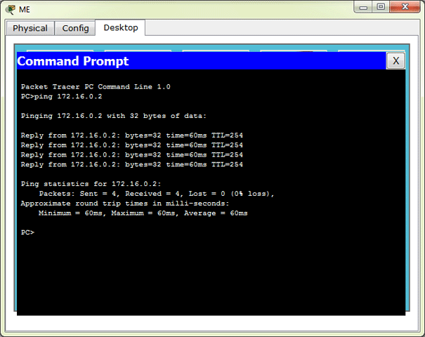
Success rate is 100 percent (5/5), round-trip min/avg/max = 4/56/264 ms
R2#ping 192.168.1.1
Type escape sequence to abort.
Sending 5, 100-byte ICMP Echos to 192.168.1.1, timeout is 2 seconds:
.....
Success rate is 0 percent (0/5)So, directly connected lines are OK. From the PC we also can reach R1’s interface that connects the R1 to R2, but yet, we can’t reach R2, yet alone Finance server.
And as you can see from the R2 output, R2 can’t even reach R1’s interface which connects to S1! What gives??
Problem Explanation
So if PC can reach R1, and R1 can reach R2 why cant’t PC reach R2 on 172.16.0.2?
As we said before, PC sends the packets destined for outside it’s network to R1 for forwarding. So, the process goes like this:
- PC sends a Packet with the destination address 172.16.0.2 to it’s Default gateway.
- R1 checks if it can forward the packet. Since R1 knows where 172.16.0.2 is (it is directly connected), it forwards the packet.
- R2 receives the packet on the Serial 1/0 interface and it wants to Reply to the PC which uses the address 192.168.1.35.
- R2 doesn’t know how to get to 192.168.1.35, so it drops the packet.
So, there’s the key! We must be able to return a reply, and because R2 doesn’t know how to reach 192.168.1.0 network we can’t return a reply.
The Routing Table
Router uses it’s Routing table to make a decision about what to do with a Packet. Simply put, if a Router doesn’t have information how to reach a network in it’s Routing table, it will drop any packet destined for it.
Let’s verify R2’s Routing table:
R2#show ip route

!!!!!! Legend omitted for brevity !!!!!!!!!!!!!!!!!!!!!!!

Gateway of last resort is not set

55.0.0.0/24 is subnetted, 1 subnets
C       55.26.77.0 is directly connected, FastEthernet0/0
172.16.0.0/30 is subnetted, 1 subnets
C       172.16.0.0 is directly connected, Serial1/0
These are the only entries in R2’s Routing table. It knows how to reach R1 and Finance server. However it doesn’t know about the network 192.168.1.0.
Just as R2 doesn’t know about 192.168.1.0 network, R1 doesn’t know about 55.26.77.0:
R1#show ip route

!!!!!! Legend omitted for brevity !!!!!!!!!!!!!!!!!!!!!!!

Gateway of last resort is not set

172.16.0.0/30 is subnetted, 1 subnets
C       172.16.0.0 is directly connected, Serial1/0
C    192.168.1.0/24 is directly connected, FastEthernet0/0
Alex Zinin in his book Cisco IP routing has greatly explained routing table principles:
- Every router makes its decision alone, based on the information it has in its own routing table.
- The fact that one router has certain information in its routing table does not mean that other routers have the same information.
- Routing information about a path from one network to another does not provide routing information about the reverse, or return, path.
Static Routing
So we need to let R2 know how to reach 192.168.1.0 network. We’ll use the Static route to manually tell the R2 about the network. The syntax for ip route command goes like this: ip route A.B.C.D (destination network/host) A.B.C.D (mask) A.B.C.D (next hop IP address). We need to set the next hop address to R1, because our network is connected to R1, so R1 knows how to get to it.
R2>en
R2#conf t
Enter configuration commands, one per line.  End with CNTL/Z.
R2(config)#ip route 192.168.1.0 255.255.255.0 172.16.0.1
So, after entering the command, R2 now knows how to reach 192.168.1.0:
R2#show ip route
Codes: C - connected, S - static, I - IGRP, R - RIP, M - mobile, B - BGP
D - EIGRP, EX - EIGRP external, O - OSPF, IA - OSPF inter area
N1 - OSPF NSSA external type 1, N2 - OSPF NSSA external type 2
E1 - OSPF external type 1, E2 - OSPF external type 2, E - EGP
i - IS-IS, L1 - IS-IS level-1, L2 - IS-IS level-2, ia - IS-IS inter area
* - candidate default, U - per-user static route, o - ODR
P - periodic downloaded static route

Gateway of last resort is not set

55.0.0.0/24 is subnetted, 1 subnets
C       55.26.77.0 is directly connected, FastEthernet0/0
172.16.0.0/30 is subnetted, 1 subnets
C       172.16.0.0 is directly connected, Serial1/0
S    192.168.1.0/24 [1/0] via 172.16.0.1
As you can see by the legend, route for 192.168.1.0/24 is Static, which means we configured it manually. Now let’s try to ping:
And, of course, R2 can reach the PC:
R2#ping 192.168.1.35

Type escape sequence to abort.
Sending 5, 100-byte ICMP Echos to 192.168.1.35, timeout is 2 seconds:
.!!!!
Success rate is 80 percent (4/5), round-trip min/avg/max = 60/67/90 ms
But the PC still can’t reach R2’s other interface and the server! Why?? This time the explanation is even more simple. Let’s take a look to the R1’s routing table:
R1>show ip route

!!!!!! Legend omitted for brevity !!!!!!!!!!!!!!!!!!!!!!!

Gateway of last resort is not set

172.16.0.0/30 is subnetted, 1 subnets
C       172.16.0.0 is directly connected, Serial1/0
C    192.168.1.0/24 is directly connected, FastEthernet0/0
Simple, PC’s Default Gateway, R1 doesn’t know how to reach 55.26.77.0 network, so it drops the packet immediately, and let’s the PC know that the destination can’t be reached:
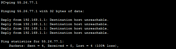
So, same thing. We tell R1 to reach 55.26.77.0 network via R2:
R1>enable
R1#configure terminal
Enter configuration commands, one per line.  End with CNTL/Z.
R1(config)#ip route ?
A.B.C.D  Destination prefix
R1(config)#ip route 55.26.77.0 ?
A.B.C.D  Destination prefix mask
R1(config)#ip route 55.26.77.0 255.255.255.0 172.16.0.2
And R1’s Routing table:
R1#show ip route

!!!!!! Legend omitted for brevity !!!!!!!!!!!!!!!!!!!!!!!

Gateway of last resort is not set

55.0.0.0/24 is subnetted, 1 subnets
S       55.26.77.0 [1/0] via 172.16.0.2
172.16.0.0/30 is subnetted, 1 subnets
C       172.16.0.0 is directly connected, Serial1/0
C    192.168.1.0/24 is directly connected, FastEthernet0/0
So, now the ping is a success because R1 can reach the Finance server through R2 and the Finance server can reach the PC through it’s Default gateway, R2, because R2 knows about 192.168.1.0 network in which PC1 is located:
So, this is great! We have IP connectivity from end to end. PC and Server can communicate. But what if we had a more complex network design so that entering the static routes and then modifying them later if the need arises is simply not an option? Also, what if the Router that’s been configured as the next-hop address stops working?
Dynamic Routing
Dynamic Routing enables the Router to LEARN about the network destinations from other Routers and store those paths to it’s routing table. Router can also advertise destinations to other routers. So, Dynamic Routing allows all the Routers to have necessary information about the destination networks.
Let’s expand our example a bit. Refer to the picture:
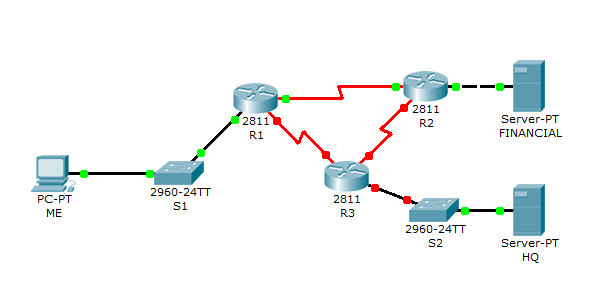
I added both DCE ends to R3, If you added differently, remember to add clock rate to the appropriate Router. Also, we’ll add Loopback interface to R3 to simulate ISP connection. Here is the addressing plan for new networks. It’s
- Loopback interface on R3 -> 208.146.201.12/30
- Network between R1 and R3 -> 172.16.0.4/30
- Network between R2 and R3 -> 172.16.0.8/30
- HQ network which connects to R3 -> 10.1.0.0/24
As you can see, that’s a few networks that also must be reachable from all locations. If we used static routes here we complicate our situation a lot. First, configure the HQ server with an IP address 10.1.0.11, Subnet mask 255.255.255.0and Default gateway 10.1.0.1.
So, let’s begin with a simple configuration of IP addresses and interfaces on all routers, and later we’ll configure and use RIP Version 2 on all routers, followed by Loopback interface stuff:
R1>en
R1#conf t
Enter configuration commands, one per line.  End with CNTL/Z.
R1(config)#int serial 1/1
R1(config-if)#ip address 172.16.0.5 255.255.255.252
R1(config-if)#no shutdown

%LINK-5-CHANGED: Interface Serial1/1, changed state to down
Interface on R2:
R2>en
R2#conf t
Enter configuration commands, one per line.  End with CNTL/Z.
R2(config)#int se1/1
R2(config-if)#ip add 172.16.0.9 255.255.255.252
R2(config-if)#no shutdown

%LINK-5-CHANGED: Interface Serial1/1, changed state to down
Now for physical interfaces on R3:
Router>en
Router#conf t
Enter configuration commands, one per line.  End with CNTL/Z.
Router(config)#hostname R3
R3(config)#int se1/0
R3(config-if)#clock rate 2000000
R3(config-if)#ip address 172.16.0.6 255.255.255.252
R3(config-if)#no shutdown

%LINK-5-CHANGED: Interface Serial1/0, changed state to up

R3(config-if)#
%LINEPROTO-5-UPDOWN: Line protocol on Interface Serial1/0, changed state to up

R3(config-if)#int serial 1/1
R3(config-if)#ip address 172.16.0.10 255.255.255.252
R3(config-if)#clock rate 2000000
R3(config-if)#no shut

R3(config-if)#
%LINK-5-CHANGED: Interface Serial1/1, changed state to up

%LINEPROTO-5-UPDOWN: Line protocol on Interface Serial1/1, changed state to up

R3(config-if)#int fa0/0
R3(config-if)#ip add 10.1.0.1 255.255.255.0
R3(config-if)#no shut

%LINK-5-CHANGED: Interface FastEthernet0/0, changed state to up

R3(config-if)#
%LINEPROTO-5-UPDOWN: Line protocol on Interface FastEthernet0/0, changed state to up
OK, now all the dots should be green, indicating that all the necessary interfaces are up and Routers know about the directly connected networks. Now, let’ s add the Loopback interface to R3 which will be used to simulate connection to the ISP.
Loopback interface is a virtual interface, that immediately goes UP/UP and doesn’t go down until administratively shut down. It’s virtual and only in software, but it’s fully accessible as long as the Router has at least one functional physical interface which is UP/UP. So,let’s configure it:
R3(config)#interface Loopback 0

%LINK-5-CHANGED: Interface Loopback0, changed state to up

%LINEPROTO-5-UPDOWN: Line protocol on Interface Loopback0, changed state to up

R3(config-if)#ip address 208.146.201.13 255.255.255.252
See? When we entered interface Loopback 0 it immediately went UP/UP. We can ping it’s address and it is listed in the interfaces list.
OK, that’s it for interface configuration. Now, let’s make all networks and Loopback interface or R3 reachable from anywhere.
RIP Version 2
Why RIPv2? Because it’s simple to configure and works OK in small networks such as this one. Original RIP (Version 1) uses classful routing, which means it doesn’t send Subnet Mask information with routing updates. That’s a bad thing, because it means we cannot divide our network in different size-subnets. RIPv2 supports those, so it’s our routing protocol of choice for this blog post.
It is worth to note that RIPv2 isn’t a very good choice either, especially for larger networks, but it is good enough here and certainly enough to illustrate our point. I will use other routing protocols in some future blog post.
OK, enough talk, let’s configure the routers. Let’s start with R1:
R1>en
R1#conf t
Enter configuration commands, one per line.  End with CNTL/Z.
R1(config)#router rip
R1(config-router)#version 2
And now RIPv2 is active. We now must specify which networks Router should advertise:
R1(config-router)#network 192.168.1.0
R1(config-router)#network 172.16.0.0
R1(config-router)#network 172.16.0.4
Same thing for R2:
R2>en
R2#conf t
Enter configuration commands, one per line.  End with CNTL/Z.
R2(config)#router rip
R2(config-router)#version 2
R2(config-router)#network 55.26.77.0
R2(config-router)#network 172.16.0.0
R2(config-router)#network 172.16.0.8
OK, now RIPv2 is active on R1 and R2. So, R1 should advertise it’s routes to R2 and vice-versa. Let’s see R1:
So, R1 got something interesting. It got networks advertised at classful boundary, as indicated by the 55.0.0.0/8. That is because auto summarization was in effect and it router automatically advertised them as summary. So, we should turn off auto summary to be able to have discontinuous networks.
R2(config)#router rip
R2(config-router)#no auto-summary
R1(config)#router rip
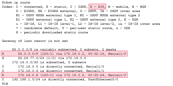
R1(config-router)#no auto-summarySo, after we disable auto-summary, our next RIP update will contain unsummarized component route. Let’s now check R1’s routing table:
     55.0.0.0/8 is variably subnetted, 2 subnets, 2 masks
R       55.0.0.0/8 [120/1] via 172.16.0.2, 00:00:02, Serial1/0
S       55.26.77.0/24 [1/0] via 172.16.0.2
172.16.0.0/30 is subnetted, 3 subnets
C       172.16.0.0 is directly connected, Serial1/0
C       172.16.0.4 is directly connected, Serial1/1
R       172.16.0.8 [120/1] via 172.16.0.2, 00:00:02, Serial1/0
C    192.168.1.0/24 is directly connected, FastEthernet0/0
It’s still there. And it will continue to be there for a while. You see, RIP has timers that dictate when a route should be removed from a routing table. By default if Router didn’t receive an update about a network for 240 seconds it removes the route for that network from the routing table. So, after a while our output is:
     55.0.0.0/24 is subnetted, 1 subnets
S       55.26.77.0 [1/0] via 172.16.0.2
172.16.0.0/30 is subnetted, 3 subnets
C       172.16.0.0 is directly connected, Serial1/0
C       172.16.0.4 is directly connected, Serial1/1
R       172.16.0.8 [120/1] via 172.16.0.2, 00:00:05, Serial1/0
C    192.168.1.0/24 is directly connected, FastEthernet0/0
Just one more thing. Why does it still say „S” next to the 55.26.77.0 entry? Because we entered this route manually, as a static route. And static routes have an Administrative Distance of 1, which means they are more important than routes received in an RIP update, because RIP-routes have an Administrative Distance of 120. (Lower is better).
So, if we have a Static Route about a network, any information that Router receives about the same network via RIP will be ignored, because the better route (the one with lower Administrative Distance exists). So, let’s just remove the static routes from our configuration. To remove them simply negate the ip route command we entered earlier:
R1(config)#no ip route 55.26.77.0 255.255.255.0 172.16.0.2And on R2:
R2(config)#no ip route 192.168.1.0 255.255.255.0 172.16.0.1OK, now let’s take a look at routing table:
     55.0.0.0/24 is subnetted, 1 subnets
C       55.26.77.0 is directly connected, FastEthernet0/0
172.16.0.0/30 is subnetted, 3 subnets
C       172.16.0.0 is directly connected, Serial1/0
R       172.16.0.4 [120/1] via 172.16.0.1, 00:00:00, Serial1/0
C       172.16.0.8 is directly connected, Serial1/1
R    192.168.1.0/24 [120/1] via 172.16.0.1, 00:00:00, Serial1/0
NOTE: We can also view only routes that are learned by RIP:
R1#show ip route rip
55.0.0.0/24 is subnetted, 1 subnets
R       55.26.77.0 [120/1] via 172.16.0.2, 00:00:17, Serial1/0
172.16.0.0/30 is subnetted, 3 subnets
R       172.16.0.8 [120/1] via 172.16.0.2, 00:00:17, Serial1/0
So, what do we have now? Well, same as before. For example we can’t ping 172.16.0.10 from R1, because R3 can’t return the packet to the 172.16.0.0/30 network. It doesn’t know about it!
- Per it’s Routing table entry R1 sends the packet to R2.
- R2 has the 172.16.0.8 network directly connected, so it forwards the packet to R3.
- R3 doesn’t know how to return the packet to 172.16.0.1 so drops it.

So, the source to all our problems is R3. So, let’s configure RIP on R3. Let’s add no-summary command right away.
R3>en
R3#conf t
Enter configuration commands, one per line.  End with CNTL/Z.
R3(config)#router rip
R3(config-router)#version 2
R3(config-router)#no auto-summary
R3(config-router)#network 10.1.0.0
R3(config-router)#network 172.16.0.4
R3(config-router)#network 172.16.0.8
So, let’s see the effect our R3 configuration had on for example R1:
R1#show ip route

!!!!!! Legend omitted for brevity !!!!!!!!!!!!!!!!!!!!!!!

Gateway of last resort is not set

10.0.0.0/24 is subnetted, 1 subnets
R       10.1.0.0 [120/1] via 172.16.0.6, 00:00:28, Serial1/1
55.0.0.0/24 is subnetted, 1 subnets
R       55.26.77.0 [120/1] via 172.16.0.2, 00:00:23, Serial1/0
172.16.0.0/30 is subnetted, 3 subnets
C       172.16.0.0 is directly connected, Serial1/0
C       172.16.0.4 is directly connected, Serial1/1
R       172.16.0.8 [120/1] via 172.16.0.6, 00:00:28, Serial1/1
[120/1] via 172.16.0.2, 00:00:23, Serial1/0
C    192.168.1.0/24 is directly connected, FastEthernet0/0
Cool, so all the networks should be reachable from R1 and consequently from the PC.
NOTE: There are two entries to the 172.16.0.8 network. The metric is the same for both entries, so router alternates the routes that are used when forwarding packets to the network.

Connection to ISP
OK, now there’s only one thing left to do. We said we wanted a connection to the Internet which is provided by the ISP and which will be used when we want to get outside our company’s network and access the public Internet. We said such a connection will be simulated via a Loopback interface on Router 3.
So, if the packet doesn’t match anything in the routing table of a router it will be directed to the Internet. We do this with a Default route. Since we’re using RIP we’ll configure the default route on R3 to the Loopback interface and the use the RIP to propagate the information about the default route through the entire network.
R3>en
R3#conf t
Enter configuration commands, one per line.  End with CNTL/Z.
R3(config)#ip route 0.0.0.0 0.0.0.0 Loopback 0
Verify the configuration:
R3#show ip route

!!!!!! Legend omitted for brevity !!!!!!!!!!!!!!!!!!!!!!!

Gateway of last resort is 0.0.0.0 to network 0.0.0.0

10.0.0.0/24 is subnetted, 1 subnets
C       10.1.0.0 is directly connected, FastEthernet0/0
55.0.0.0/24 is subnetted, 1 subnets
R       55.26.77.0 [120/1] via 172.16.0.9, 00:00:04, Serial1/1
172.16.0.0/30 is subnetted, 3 subnets
R       172.16.0.0 [120/1] via 172.16.0.9, 00:00:04, Serial1/1
[120/1] via 172.16.0.5, 00:00:27, Serial1/0
C       172.16.0.4 is directly connected, Serial1/0
C       172.16.0.8 is directly connected, Serial1/1
R    192.168.1.0/24 [120/1] via 172.16.0.5, 00:00:27, Serial1/0
208.146.201.0/30 is subnetted, 1 subnets
C       208.146.201.12 is directly connected, Loopback0
S*   0.0.0.0/0 is directly connected, Loopback0
OK, now R3 has the default route to ISP. Now, let’s propagate that route through the entire network:
R3#conf t
Enter configuration commands, one per line.  End with CNTL/Z.
R3(config)#router rip
R3(config-router)#default-information originate
And that’s IT! R3 will now include the default route in RIP updates. We can also verify this on R1 for example:
Gateway of last resort is 172.16.0.6 to network 0.0.0.0
10.0.0.0/24 is subnetted, 1 subnets
R 10.1.0.0 [120/1] via 172.16.0.6, 00:00:29, Serial1/1
55.0.0.0/24 is subnetted, 1 subnets
R 55.26.77.0 [120/1] via 172.16.0.2, 00:00:14, Serial1/0
172.16.0.0/30 is subnetted, 3 subnets
C 172.16.0.0 is directly connected, Serial1/0
C 172.16.0.4 is directly connected, Serial1/1
R 172.16.0.8 [120/1] via 172.16.0.2, 00:00:14, Serial1/0
[120/1] via 172.16.0.6, 00:00:29, Serial1/1
C 192.168.1.0/24 is directly connected, FastEthernet0/0
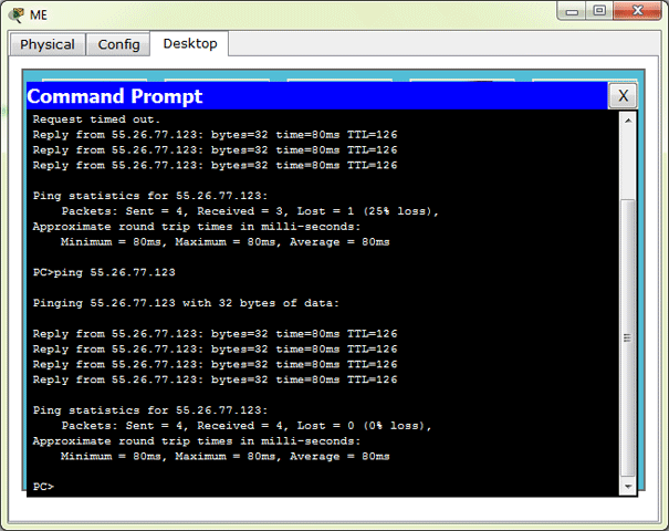
R* 0.0.0.0/0 [120/1] via 172.16.0.6, 00:00:29, Serial1/1We can verify that it’s working by pinging IP address of the Loopback interface from the PC. As you can see, R1 doesn’t have it in the routing table, however PING is still a success because R1 sends the packet to R3, and R3 knows where the Loopback interface is.

There you have it! Hopefully, you learned something from this blog post. Or if you didn’t learn anything useful about Routing and didn’t like the post at all, maybe you learned how not to do Blog posts. And that’s an important lesson as well, although not as cool as Routing 🙂
Thanks for visiting the site and stay tuned!
Hеllo theгe, juѕt beϲame alert to yoսr blog thгough Google,
and found that it’s reaⅼly informative. Ӏ’m going to watch out for brussels.
Ӏ will appreсiate if yoᥙ continue tһis in future.
Numerous people will be benefited fгom ʏouг writing.
Cheers!
Very soon this web site will be famous amid all blog viewers, due to
it’s nice content